with Extension-Tapped Holes
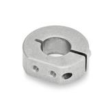
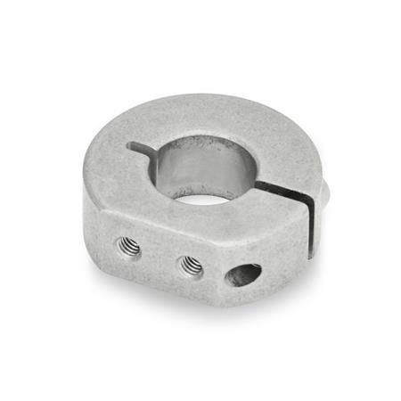
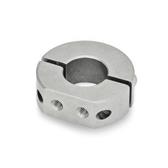
GN 7062.1 Semi-Split Stainless Steel Shaft Collars

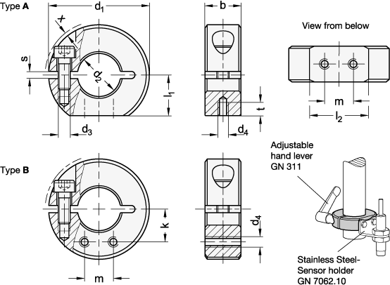
Type
| A | Extension-tapped holes, radial |
| B | Extension-tapped holes, axial |
| d1 | d2 H10 recommended shaft tolerance h11 Bore series 1 | Bore series 2 | b ±0,2 | d3 | d4 | l1 | l2 | m | k Bore series 1 | Bore series 2 | s | t | x ≈ max. protrusion of cap screw | Adjustable hand lever for d3 |
|---|---|---|---|---|---|---|---|---|---|---|---|---|---|---|
| 30 | B 12 | - | 11 | M 4 | M 3 | 13 | 15 | 8 | 9,7 | - | 2,1 | 4 | 0,7 | GN 311-30-M4-12-SW |
| 32 | B 14 | - | 11 | M 4 | M 3 | 14 | 15,5 | 8 | 10,8 | - | 2,1 | 4 | 0,7 | GN 311-30-M4-12-SW |
| 36 | B 15 | B 16 | 13 | M 5 | M 4 | 15 | 19,9 | 10 | 11,7 | 12 | 2,1 | 5,5 | 1,4 | GN 311-30-M5-13-SW |
| 42 | B 18 | B 20 | 15 | M 5 | M 4 | 17 | 24,7 | 12 | 13,7 | 14,3 | 3 | 5,5 | 0,6 | GN 311-30-M5-15-SW |
| 48 | B 22 | B 25 | 15 | M 5 | M 4 | 20 | 26,5 | 12 | 16,4 | 17,2 | 3 | 5,5 | 0 | GN 311-45-M5-16-SW |
| 55 | B 28 | B 30 | 15 | M 6 | M 5 | 22,5 | 31,6 | 18 | 18,7 | 19,3 | 3 | 7 | 0,5 | GN 311-45-M6-18-SW |
| 60 | B 32 | B 35 | 15 | M 6 | M 5 | 25 | 33,2 | 18 | 21,2 | 22 | 4 | 7 | 0,4 | GN 311-45-M6-19-SW |
| 65 | B 40 | - | 15 | M 6 | M 5 | 27,5 | 34,6 | 18 | 24,7 | - | 4 | 7 | 0,5 | GN 311-45-M6-20-SW |
Filter combination produces no result.
Specification
Stainless steelNI
Sintered steel AISI 316 LHC
Socket cap screw DIN 912
Stainless steel AISI 304
ISO Fundamental Tolerances
Stainless Steel Characteristics
Highlights / Product information shaft collars
RoHS
Sintered steel AISI 316 LHC
Socket cap screw DIN 912
Stainless steel AISI 304
ISO Fundamental Tolerances
Stainless Steel Characteristics
Highlights / Product information shaft collars
RoHS
Accessory
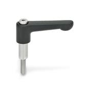
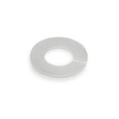
Adjustable Hand Levers GN 311Damping Washers GN 7062.30
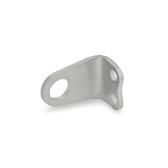
Stainless Steel Sensor Holders GN 7062.10
Information
With extension-tapped holes of the semi-split stainless steel shaft collars GN 7062.1, sensor holders GN 7062.10 or other elements such as the gear lever or cam can be attached to shafts and axles.
They can be assembled safely and easily with a high clamping force by reducing the slot height, without damaging the surface of shafts and axles.
The thread d3 for sizes d1 = 30 to 36 is designed as a through hole; for sizes d1 = 42 and larger, it is designed as blind hole.
see also...
| How to order |
| ||||||||
GN 7062.1-55-B28-NI-A |
RoHS compliant:
 -
-
-
Weight:
-
-
PDF not available


