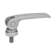
with Threaded Stud, Contact Plate Plastic
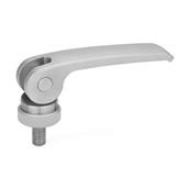
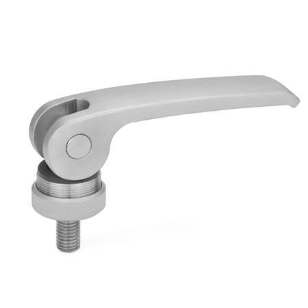
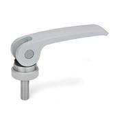
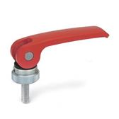
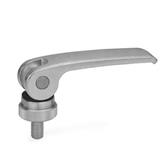
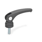
GN 927.5 Stainless Steel Clamping Levers with Eccentrical Cam, Lever Stainless Steel
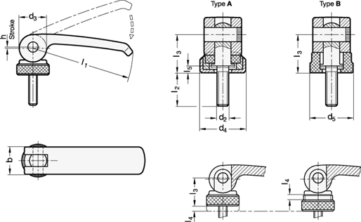
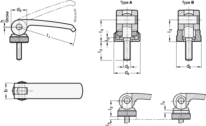
Type
| A | Plastic contact plate with setting nut |
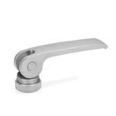
| B | Plastic contact plate without setting nut |
| l1 | d2 | l2 in clamping position | b | d3 | d4 | d5 | h stroke at 90° lever movement | l3 in clamping position | l4 Ad- justable range | l5 in clamping position | ||||||
|---|---|---|---|---|---|---|---|---|---|---|---|---|---|---|---|---|
| 44 | M 4 | 12 | 16 | 20 | 25 | 30 | - | - | 12 | 12 | 15 | 14 | 0,5 | 13,2 | 2 | 2,2 |
| 44 | M 5 | 12 | 16 | 20 | 25 | 30 | 35 | 40 | 12 | 12 | 15 | 14 | 0,5 | 13,2 | 2 | 2,2 |
| 63 | M 5 | 16 | 20 | 25 | 30 | 35 | 40 | 50 | 16 | 16 | 19 | 18,5 | 0,75 | 16,3 | 2,5 | 3 |
| 63 | M 6 | 16 | 20 | 25 | 30 | 35 | 40 | 50 | 16 | 16 | 19 | 18,5 | 0,75 | 16,3 | 2,5 | 3 |
| 82 | M 6 | 20 | 25 | 30 | 35 | 40 | 50 | 60 | 20 | 20 | 25 | 22,5 | 1 | 19,5 | 3 | 3,7 |
| 82 | M 8 | 20 | 25 | 30 | 35 | 40 | 50 | 60 | 20 | 20 | 25 | 22,5 | 1 | 19,5 | 3 | 3,7 |
| 101 | M 8 | 20 | 25 | 30 | 35 | 40 | 50 | 60 | 25 | 26 | 30 | 27 | 1,5 | 25,3 | 4 | 4,8 |
| 101 | M 10 | 20 | 25 | 30 | 35 | 40 | 50 | 60 | 25 | 26 | 30 | 27 | 1,5 | 25,3 | 4 | 4,8 |
Filter combination produces no result.
Specification
Lever
Stainless steel (precision casting)
AISI CF-8
Axis, lag screw
Setting nut and setting screw (type A)
Stainless steel AISI 303
Contact plate
Clamping and Manual Forces
https://www.youtube.com/watch?v=WAXDnI1X7Z4
Plastic Characteristics
Stainless Steel Characteristics
RoHS
Stainless steel (precision casting)
AISI CF-8
Axis, lag screw
Setting nut and setting screw (type A)
Stainless steel AISI 303
Contact plate
- Type A
Technopolymer (Polyacetal POM)
Glass fiber reinforced
- Type B
Technopolymer (Polyamide PA)
Glass fiber reinforced
Clamping and Manual Forces
https://www.youtube.com/watch?v=WAXDnI1X7Z4
Plastic Characteristics
Stainless Steel Characteristics
RoHS
Information
Stainless steel clamping levers with eccentrical cam GN 927.5 are used for rapid clamping and releasing. Hereby, contrary to a clamping operation via a thread, these levers permit a torque-free clamping.
The lever has been designed to ensure that its movement cannot exceed the max. clamping force. There are no loose components since they are all assembled and mounted in their correct order.
The type A has the following benefits:
The distance between the lever cam and the clamping surface is adjustable via a fine pitch thread, allowing the clamping position to be set easily with maximum clamping force. Also, the position of the lever relative to the clamping axis can be determined.
| How to order |
| ||||||||
GN 927.5-82-M8-25-A |
This could also be interesting...
 GN 926.1
Clamping Levers with Eccentrical Cam (Plastic / axis, Stainless Steel threaded body)
 GN 927.4
Clamping Levers with Eccentrical Cam, Lever zinc die casting (Lever, zinc die casting / axis, Stainless Steel threaded body / plastic contact plate)
 GN 927
Clamping Levers with Eccentrical Cam, Lever zinc die casting (Lever, zinc die casting, Steel threaded body, zinc-plated / plastic contact plate)
 GN 927.3
Clamping Levers with Eccentrical Cam, Level steel (Lever, axis, Steel threaded body, zinc-plated / plastic contact plate)
 GN 926
Clamping Levers with Eccentrical Cam (Plastic / axis, Steel threaded body, zinc-plated)
 GN 927.7
Stainless Steel Clamping Levers with Eccentrical Cam, Lever stainless steel (all parts in Stainless Steel)
 GN 927.5
Clamping Levers with Eccentrical Cam with Internal Thread, Lever Stainless Steel
RoHS compliant:
 -
-
-
Weight:
-
-
PDF not available
