for Welding
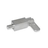
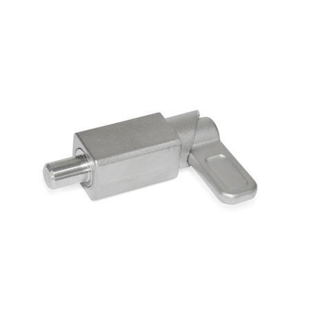
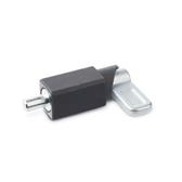
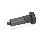
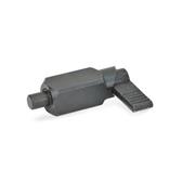
GN 722.1 Stainless Steel Spring Latches
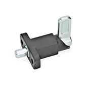
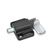
Type
| A | Latch riveted, not removable |
| AU | Latch screwed, removable |
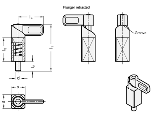
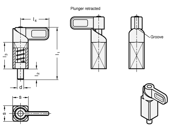
| d Pin -0,05/-0,25 Bore +0,1/+0,3 | s | l1 ≈ | l2 | l3 | l4 | A/F Type AU | Spring load in N ≈ initial | end |
|---|---|---|---|---|---|---|---|---|
| 8 | 20 | 54 | 14 | 35 | 37 | 2,5 | 15 | 50 |
| 10 | 20 | 54 | 14 | 35 | 37 | 2,5 | 15 | 50 |
| 12 | 20 | 54 | 14 | 35 | 37 | 2,5 | 15 | 50 |
| 14 | 20 | 54 | 14 | 35 | 37 | 2,5 | 15 | 50 |
| 16 | 30 | 83 | 20 | 54 | 55 | 4 | 30 | 110 |
| 20 | 30 | 83 | 20 | 54 | 55 | 4 | 30 | 110 |
Specification
Stainless steel precision castingA4
- Weldable
- AISI 316
Plunger pin
Stainless steel AISI 316
Pressure spring
Stainless steel AISI 316Ti
RoHS
Information
With stainless steel spring latches GN 722.1, the plunger pin is retracted over the curve of the guide by a 180° turn of the latch. The notch at the upper end of the curve causes the latch to be held in place if the plunger pin needs to be kept temporarily from protruding. The stainless steel A4 version is suitable for use in particularly aggressive environments.
The dimensional tolerances between plunger pin and guide are selected so that the functional reliability is guaranteed even after welding, applying a corrosion protection layer or in case of contamination.
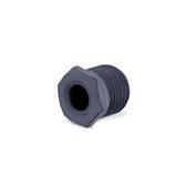
For fastening by welding, the unmounted type AU is particularly recommended to avoid changes to the microstructure of the material due to heating of the spring and plunger pin. In this case, the indexing plunger is assembled only after the surface treatment of the welded guide.
see also...
| How to order |
| ||||||||
GN 722.1-8-20--AU-A4 |
This could also be interesting...
 GN 722.1
Spring Latches, for Welding
 GN 722.2
Spring Latches with Flange for Surface Mounting, Right-Angled to the Plunger Pin
 GN 722.3
Spring Latches with Flange for Surface Mounting, Parallel to the Plunger Pin
-
GN 722.1
Spring Latches, for Welding
 GN 412.2
Positioning Bushings for Indexing Plungers
 GN 618
Indexing Plungers for Welding
 GN 612.3
Cam Action Indexing Plungers for Welding
 -
-
-
-


